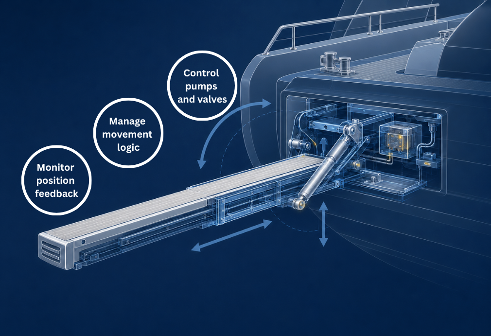
To the operator, a hydraulic gangway or swim platform may appear to respond to a single extend or retract command. Behind that command, however, the control system may need to release a locking mechanism, activate the hydraulic power unit and the appropriate directional valves, monitor position signals and determine when the next movement can begin.
Hydraulic power provides the force required for movement. The electronic controller coordinates the sequence and determines when and how the individual components are activated.
A programmable electronic controller can execute the required sequence, evaluate predefined operating conditions, monitor sensor feedback and communicate system status or faults to an HMI or onboard network.
For boat builders, OEMs and system integrators, the key design question is therefore not only how many outputs are required. The controller architecture must also match the signal types, valve loads, diagnostic requirements, communication interfaces and expected system response in the event of a fault.
What happens after the operator presses extend?
In practice, the requested movement can involve several coordinated functions, such as:
- unlocking a mechanical locking mechanism
- lifting or lowering the structure
- extending or retracting one or more sections
- rotating or positioning the gangway
- activating the hydraulic power unit
- controlling directional valves
- monitoring intermediate and final positions
- confirming that the mechanism has reached the requested position
- transmitting operating status or fault information to an HMI.
The electronic controller coordinates these functions according to a predefined application sequence.
The exact sequence always depends on the mechanical and hydraulic design of the gangway or platform. A simple system may require only a few inputs and outputs, while a more automated application may include several sensors, valves, operating modes and movement conditions.
How a typical gangway control sequence works
A simplified gangway extension sequence could work as follows:
- The operator activates the gangway using a switch, keypad, remote control or HMI.
- The controller receives the command and verifies whether the predefined operating conditions are met.
- If the gangway is secured by a locking mechanism, the controller initiates the unlocking sequence.
- After receiving confirmation that the mechanism is released, the controller activates the hydraulic power unit.
- The appropriate directional valve is energized to start the requested movement.
- During movement, the controller monitors limit switches, position sensors or other feedback signals.
- When the target position is reached, the corresponding output is deactivated.
- The system confirms the gangway position and communicates the status to the operator interface.
The electronic controller therefore acts as the central logic unit of the application. It receives commands and feedback, evaluates operating conditions and determines which output should be activated next.
Depending on the application, the sequence may also include time delays, intermediate positions, manual operating modes or fault handling if an expected signal is not received.
Defining inputs, outputs and feedback signals
Selecting a controller based only on the number of inputs and outputs can result in an unsuitable architecture. The electrical characteristics of each signal and load must also be considered. The control system connects the operator interface, hydraulic components and position feedback within one application.
Operator inputs
Commands can originate from:
- mechanical switches
- control panels
- keypads
- remote-control receivers
- HMIs
- multifunction displays
- another controller within the onboard network.
Sensor and status inputs
The controller may process signals from:
- limit switches
- position sensors
- locking-mechanism feedback
- pressure switches
- current monitoring functions
- system release signals
- other onboard electronic modules
Controlled outputs
Directional valves are commonly controlled using on/off outputs. Some applications may use proportional valves to adjust movement speed or provide smoother acceleration and deceleration.
In these cases, the controller may require PWM-capable outputs, suitable current capacity and current measurement. The output specification must always be matched to the electrical characteristics of the valve coil under the expected operating and temperature conditions.
Depending on the design, the controller can operate:
- directional valves
- proportional valves
- locking or release mechanisms
- relays
- warning indicators
- audible signals
- status outputs for another system
By processing these signals within a programmable controller, the application logic can be adapted to the specific movement sequence and equipment configuration.
How the controller uses position feedback
Position feedback does more than indicate the current state of the mechanism. It allows the controller to stop an active output, confirm that a movement has been completed or permit the next step in the sequence. Limit switches or position sensors can indicate whether the mechanism is:
- extended or retracted
- raised or lowered
- locked or released
- in an intermediate position
- ready for the next movement step
Based on this feedback, the programmed sequence can continue only after the required position or status has been confirmed. Position feedback also helps prevent the hydraulic system from continuing to operate after the required position has been reached. This can reduce unnecessary pump operation and component stress while supporting consistent movement during everyday use.
The type and number of sensors depend on the level of automation and the mechanical design of the system.
Application-Specific Interlocks
Moving gangways and swim platforms can create safety risks if functions are activated in the wrong order or under unsuitable conditions.
Control electronics can support application-specific safety interlocks, such as:
- preventing gangway or platform movement while a locking mechanism is engaged
- allowing extension only after another component reaches a defined position
- blocking simultaneous commands in opposing directions
- preventing the next sequence step if the required feedback signal is missing
- disabling movement under predefined fault conditions
The controller can execute these functions as part of the programmed application logic. However, the complete operating and safety concept must always be defined according to the mechanical design, risk assessment and applicable requirements of the complete system. These software-based interlocks support the overall safety concept but do not replace the system-level risk assessment or any required safety-rated hardware.
Stand-alone or networked control
A gangway or swim platform controller can operate as an independent system or as part of a wider onboard network.
Stand-alone control
In a stand-alone architecture, the controller is connected directly to the switches, sensors, pump and valves used by the application.
This approach may be suitable when:
- the gangway or platform operates independently
- only local controls are required
- the number of inputs and outputs is limited
- communication with other onboard systems is not required
Networked control
In a connected architecture, commands and status information can also be exchanged through a CAN-based network.
This can allow the system to communicate with:
- HMIs
- keypads
- multifunction displays
- gateways
- central control systems
- additional electronic controllers
A networked architecture can provide the operator with information about the current position, operating status or detected faults. It can also make it easier to integrate the gangway or swim platform into a wider digital switching or boat-control system. For manufacturers offering several product variants, a modular control architecture can also simplify adaptation to different boat models, feature levels and equipment configurations.
Compact and programmable control electronics
Installation space is often limited near hydraulic equipment. At the same time, electronic components may be exposed to moisture, dust, temperature changes and vibration. Compact and sealed controllers can be installed closer to the application, helping to reduce long wiring runs and simplify the overall system architecture. Configurable inputs and outputs also allow one control unit to process operating commands, position feedback and actuator outputs within the same application.
Depending on the requirements, the same controller platform can be programmed for different gangway or swim platform variants. This can help manufacturers create a scalable control concept while adapting the functional sequence to each individual product.
What OEMs should define before selecting a controller
Before selecting the control electronics, the functional requirements of the application should be clearly defined. Important questions include:
- Which individual movements must be controlled?
- In which order should these movements occur?
- How many hydraulic valves and pump outputs are required?
- What are the voltage and current requirements of the connected loads?
- Which limit switches or position sensors are available?
- Which conditions must be met before each movement is allowed?
- How should the system respond if an expected signal is not received?
- Is a manual operating or service mode required?
- Should the controller operate as a stand-alone unit?
- Is CAN communication or integration into an NMEA 2000 network required?
- Should the system exchange commands or status information with an HMI?
- Will the same controller platform be used across several product variants?
- What environmental protection is required at the installation location?
Starting with a clearly defined functional sequence makes it easier to select suitable control electronics and develop dependable application logic.
Developing a gangway or swim platform control system?
Depending on the required I/O count, valve loads and network architecture, programmable controllers such as the MRS CC16WP and MRS CC27WP can be considered for hydraulic gangway and swim platform applications.
These controllers provide configurable inputs and outputs, CAN communication and diagnostic functions in compact housings rated to IP6K8. Available features depend on the selected controller and product variant, and the specified protection rating depends on correct installation.
MRS controllers can operate locally or become part of a wider CAN-based onboard architecture. This allows the application to combine hydraulic control logic, sensor processing, diagnostics and communication with an HMI or central vessel control system.
Learn more about our marine hydraulic control solutions and compact CAN controllers for boats and yachts.
Discuss your application
Share your required movements, valves, sensors and communication interfaces with our team.
We can support you in defining a compact and programmable control architecture based on the required movements, loads, feedback signals and communication requirements of your gangway or swim platform application.
Contact us!